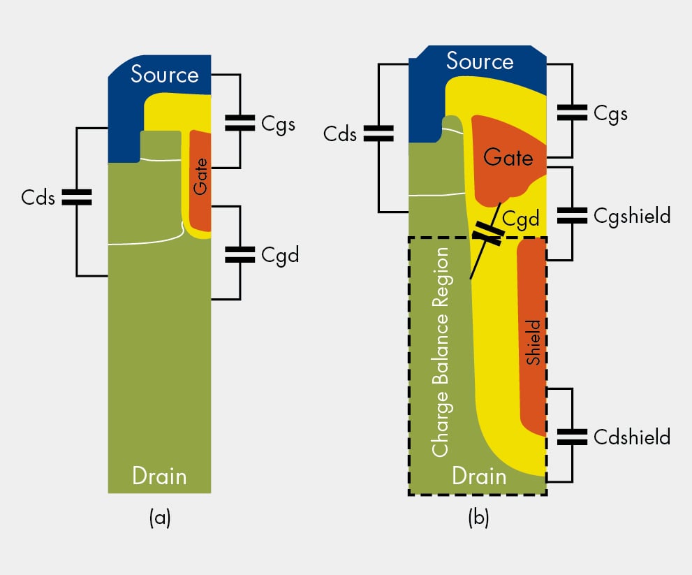
MOSFET characteristics, both with a curve tracer and with special-purpose test circuits. Testing Power MOSFETs on a curve tracer is a simple matter, provided the broad correspondence between bipolar transistor and Power MOSFET features are borne in mind. Table 1 matches some features of Power MOSFETs wi th their bipolar counterparts. 3 Performance index of Power MOSFET, calculated by multiplying the on-resistance by the gate-drain charge (100°C junction temperature). Smaller values indicate better performance; 4 Stray capacitance between Gate and Drain existing in MOSFET structure (Crss) 5 Frequency that determines the ON/OFF timing of the switching element in an inverter.
MOSFET Characteristics Viewer
The Characteristics Viewer tool lets you study characteristics of a particular parameterization of a surface-potential-based MOSFET block and match the block behavior to a set of target characteristics. The tool allows you to:
Plot simulated data, using the current block parameters.
Overlay simulated data plots over tabulated target data.
Modify block parameters. Get mac os high sierra.
When satisfied with the results of the parameters tuning in the Characteristics Viewer, update the block parameters in the model.
Save generated parameter sets for future reuse in a different model. Docker home.
Suggested Workflow
The Characteristics Viewer tool is available for surface-potential-based N-Channel MOSFET or P-Channel MOSFET blocks only. To switch to a surface-potential-based variant when you add an N-Channel MOSFET or P-Channel MOSFET block from the library, right-click the block in your model and, from the context menu, select Simscape > Block choices > Surface-potential-based. Then, when you right-click the block again, the context menu will contain the Electrical option, necessary to start the parameterization tool.


To use the MOSFET parameterization tool:

Right-click a surface-potential-based MOSFET block in your model and, from the context menu, select Electrical > Explore characteristics. A
charactericViewerwindow opens.Double-click Add characteristics. Specify the characteristics type (target, simulated, or both), and the desired values. Click Add to plot.
Continue adding more characteristics, as needed. The Replace plot button lets you replace previously added plots. You can also use the block, iteratively with Add characteristics, to configure your characteristics set.
Double-click Choose parameters and select the parameters of interest.
Double-click Generate plots.
Iterate between the previous two steps to tune the parameters by matching the simulation results to the target curves.
When satisfied with the results of the parameters tuning, double-click Update starting block parameters to update the block parameters in your model. Until you perform this step, the block in the original model is not affected.
You can double-click Save data to save the generated characteristics as a MAT-file, for future reuse in a different model.
Add and Manage Characteristics

You start the MOSFET parameters tuning process by specifying the desired set of target characteristics:
In the
charactericViewerwindow, double-click Add characteristics.The Characteristics window opens.
Enter Plot number. This number defines the number of the figure that the characteristic will be plotted on. It allows you to add multiple characteristics to the same figure, for overlaying characteristics on top of each other. However, the figure will comprise one
xy-axis only.Specify the Characteristic type:
Target only— The plot will contain data that you specified, in terms of both input and output values. No simulation will be performed in this case. The data will simply be added to the appropriate plot.Simulated only— The plot will contain data that is a result of a simulation over the input bias conditions that you specify.Target and simulated— The plot will contain both types of data. This option is useful if you are trying to adjust parameters for the model to fit data that you have extracted from a datasheet.
Select Sweep type, which defines the
x-axis variable for the resultant plot:V_GS— Sweep over the gate-source voltage.V_DS— Sweep over the drain-source voltage.I_D— Sweep over the drain current. Normally, the drain current is not a typical input for a characteristic sweep.
If the Characteristic type is
Simulated only, specify Sweep range. This is a vector of values indicating the range for the swept variable. Only the minimum and maximum values of this vector are utilized by the tool, since the exact sample points for the output data are determined by the variable-step simulation.If the Characteristic type is
Target onlyorTarget and simulated, specify Sweep values. This is a vector of values for the swept variable at which the output is sampled for the target data. As an example, for an I_D-V_DS characteristic extracted from a datasheet, the vector would contain the V_DS values corresponding to the sampled I_D values in the target curve.Select Step type to define the second independent input bias condition. The choices are the same as for Sweep type. For example, if an I_D-V_DS curve is defined as being at a constant V_GS, choose
V_GSfor Step type.Use Step values to specify the values for the stepped variable. For example, if an I_D-V_DS curve is desired for V_GS values of 0 and 10V, set Step type to
V_GSand Step values to[0 10].Select Output type, which defines the output measurement for the characteristic. This is the
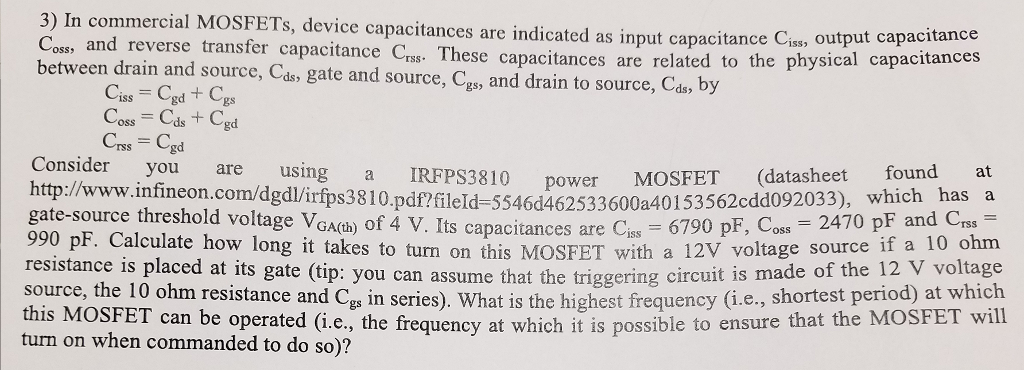
y-axis variable for the resultant plot. The available values are:V_GS,V_DS,I_D,C_GG,C_GD,C_DG, andC_DD. The capacitances C_GG, C_GD, C_DG, and C_DD are defined according to their terminals. To relate these quantities to the datasheet parameters of Ciss, Crss and Coss, note that C_GG = Ciss, C_DD = Coss, and C_GD = Crss at V_GS = 0.V_GSis not a good choice as an output for the surface-potential-based MOSFET model. This value is provided in anticipation of using this tool for other device types.If the Characteristic type is
Target onlyorTarget and simulated, specify Output values. This is the target data that you want to plot in the figures. Provide this data as anm-by-nmatrix, wheremis the size of Step values andnis the size of Sweep values.Click Add to plot to add the characteristic specification to the appropriate Plot number.
Continue adding more characteristics, as needed.
The Replace plot button lets you replace previously added plots. You can also use the block, iteratively with Add characteristics, to configure your characteristics set.
Choose Parameters and Generate Plots
After you have specified the desired set of target characteristics, the next step is to define the parameters for the MOSFET block:

In the
charactericViewerwindow, double-click Choose parameters.The Tuner window opens. It contains a series of sliders on different tabs, according to which feature of the MOSFET characteristics is most impacted by the specific parameter:
The VT tab displays parameters that primarily impact the threshold voltage (gamma and phib2ref).
The parameters on the DC tab primarily affect the DC characteristics.
The parameters on the AC tab primarily affect the MOSFET dynamics.
The parameters on the T tab affect temperature scaling.
The parameters on the FIXED tab are generally fixed at some particular value that is not easy to derive from the displayed characteristics, such as the simulation temperature and the gate resistance (which is often indicated directly on datasheets).
The EXTRAS tab contains other parameters, which impact the characteristics in ways similar to parameters that already appear on other tabs. For example, Rsref (the series resistance associated with the source) operates similarly to betaref from the DC tab. As a result, it is not always possible to disentangle these two effects.
Use the sliders on the appropriate tabs of the Tuner dialog.
You can modify the
minandmaxvalues, as needed, because they simply define the range over which the various sliders work. Photoshop crack torrent mac. These values have no meaning for the underlying model parameters. Changing aminormaxvalue automatically updates the slider range, without needing to click or .After adjusting the sliders, generate the plots to see how close the simulation data is to the target data. In the
charactericViewerwindow, double-click Generate plots.Iterate between tuning the parameters and generating plots until the simulation results match the target curves.
Power Mosfet Cross
Save the Results
Once you are satisfied with the results of the parameters tuning:
Double-click Update starting block parameters to update the block parameters in your model. Until you perform this step, the block in the original model is not affected.
Note
For this step to work, the original model must stay open while you are tuning the parameters.
You can also double-click Save data to save the generated characteristics as a MAT-file, for future reuse in a different model. Specify the file name for saving the data. Inside the file, all the data is saved in an object named
parameterHelper.To apply the parameters stored in this object to another MOSFET block, select the MOSFET block in a model and, in the MATLAB® Command Window, type:
This command applies the parameter values to the block defined by the handle
gcbh.You can also use a string instead of the block handle, for example:
To inspect the parameters directly, type
parameterHelper.parameters.valuesfor the values (stored as character vectors) orparameterHelper.parameters.namesfor the names.
Crss Mosfet Capacitance
Related Topics


